
About Compiling
I just want to show a small snippet of my C code. This uses indirection to allow for multiple port setups on one micro. Note this is C, not C++. There is a limited stack size and this limits the number of calls to functions and data that can be passed. Some code might be on an interrupt from the main file. When the code is compiled in MPLAB you check the disassembly to make sure the code is efficient and that the compiler compiled the machine code correctly. You have to be mindful that the code pages are correct too.
This code would run on a PIC16F877 along with other micros. Note that the PIC16F18877 has a lot more program memory and RAM. I’m going to have a look at MCC because it has pre-tested code libraries and sounds cool. MCC seems to be programmed visually similar to Unreal Engine 4 Blueprints with a visual editor.
If looking to use a different variant then all you do is check the datasheet and the structure can be created and set to different registers. The memory arrangement can be different too. This code is for the hardware USART, not a software one. I wrote this code nearly 20 years ago! This was using the HiTech C compiler. This has now changed to XC8 but I have not tried compiling on that C compiler yet.
Ok, so in XC8 to do the inline function you insert the ‘inline’ keyword on the function declaration, however, it does not work on the free compiler version, you have to use optimization on the paid XC8 instead. Not finished testing the compilation at all yet, in between doing a team leadership course I might get to finish trying the compilation. I have done the compiling now and it is supported but I admit I can’t be bothered to check the assembly from the disassembled code, then again it is 2am on bank holiday Monday and I have an assignment due tomorrow too.
I should say that in effect an inline function is like a macro as inline functions are not really function calls at all, in the machine code.
About the ‘Byte’
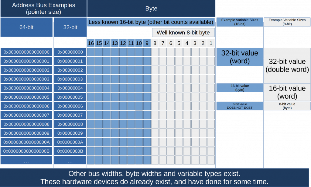
For the benefit of PC programmers, an important note here about uint8_t this is an 8-bit unsigned integer which in some cases is a byte and that is true of the PIC16F877 and an IBM PC as well. You can still address 8-bit bytes in memory on a 64bit PC. However, some of our code was being designed for the TI MSP430 which are 16-bit bytes. Yes, that is correct 16 bit bytes. Yes, it is a bit confusing and does hurt your brain when you are normally using an 8-bit byte. It is because the MSP430 has the smallest addressable unit that is 16-bit, you cannot address an 8-bit memory location because they are 16 bit. This is because on an MSP430 it is 16-bit and not 8-bit like the PIC16F877 and IBM based PCs are 8-bit. When a byte is referred to as 8-bit that is the ‘norm’ but is not actually a fixed rule. So you might ask, how do you use 8-bit data in an MSP? Well, you have two choices, share a 16-bit byte by using two halves or waste 8 bits of the 16-bit byte. To take advantage of the speed of a 16-bit device you would be better off wasting the memory space if you are thinking of transmitting 8-bit data.
You might see I’ve repeated myself a few times in the paragraph above, that’s not accidental.
Code Example
I’ve just looked at some C code I wrote a very very long time ago. (Which has been changed by others since.) Looking at the assembly and the header files.
void UsartTransmitByte(USART_PORT_handle usartPortSTRUCT, uint8_t txData)
{
	*usartPortSTRUCT->txRegister = txData;
}
There are a few problems:
- It is not portable between PICs because the handling of pointers is different and changes the timing – that could be a general problem too. There could be a floor with interrupts in this code but that would take more analysis.
- Really inefficient which will be shown in the disassembly below (but it is a trade-off)
- Someone moved it to a different architecture! PIC16F -> PIC18F (taking time to look at the disassembly)
- Thank god I know some assembly. 😐
Debugging with MPLab X IDE with a simulator:
// XC8 - free version - compiler output
// Note, that the disassembly is overlayed with simulation values
// Doing a call to test the code with a value to send of 0x55
               UsartTransmitByte(&usartPort, 0x55);
// This is setting up the stack to call (hence inline would really be a good idea)
FFA4  0E01     MOVLW 0x1
FFA6  6E12     MOVWF __pcstackCOMRAM, ACCESS ; loading stack
FFA8  0E00     MOVLW 0x0
FFAA  6E13     MOVWF 0x13, ACCESS
FFAC  0E55     MOVLW 0x55
FFAE  6E14     MOVWF txData, ACCESS
FFB0  ECDC     CALL 0xFFB8, 0      ; calls to the program memory location of the function
FFB2  F07F     NOP
// This is the exec of the function
               void UsartTransmitByte(USART_PORT_handle usartPortSTRUCT, uint8_t txData)
               {
                   *usartPortSTRUCT->txRegister = txData;
FFB8  EE20     LFSR 2, 0x5           ; start of the function call
FFBA  F005     NOP
FFBC  5012     MOVF __pcstackCOMRAM, W, ACCESS ; accessing the stack
FFBE  26D9     ADDWF FSR2, F, ACCESS
FFC0  5013     MOVF 0x13, W, ACCESS
FFC2  22DA     ADDWFC FSR2H, F, ACCESS
FFC4  CFDE     MOVFF POSTINC2, 0x15
FFC6  F015     NOP
FFC8  CFDD     MOVFF POSTDEC2, 0x16
FFCA  F016     NOP

; *usartportSTRUCT->txRegister ... taking the txRegister's dereferenced value and putting it in the FSR2 virtual register
; preps the PIC with 0x0FAD which is the address of the tx register in the hardware
; the 0x15 and 0x16 are the two locations holding the tx regsiter
FFCC  C015     MOVFF 0x15, FSR2      ; loading the FSR2 with the stored pointer address (low byte)
FFCE  FFD9     NOP
FFD0  C016     MOVFF 0x16, FSR2H     ; loading the FSR2 with the stored pointer address (high byte)
FFD2  FFDA     NOP

; this will load the value into the location the virtual register is pointing to
FFD4  C014     MOVFF txData, INDF2   ; move the value of txData into INDF2 (virtual regsiter that uses the FSR2 value as a register location)
FFD6  FFDF     NOP
52:            }
FFD8  0012     RETURN 0 ; Returns from function with no result
Value of registers after execution:
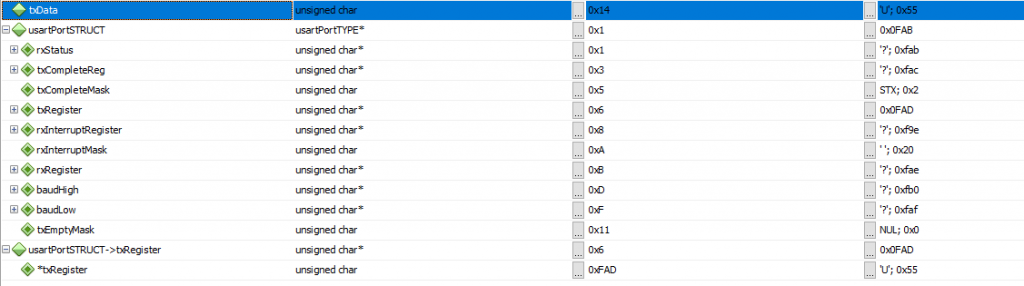
0xFAD is the transmit register – so that is correct
0x55 is loaded
Look at the IO view:
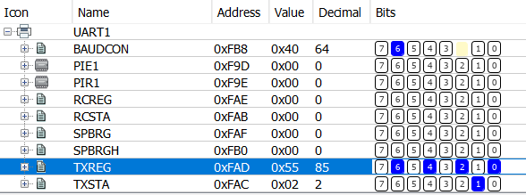
TXSTA bit 1 – Set, means the TXREG value has been transmitted and the next value can be loaded.
I’ve looked at the output and it’s actually been put on a different PIC by other engineers that I know aren’t there now. The PIC18F4620 now used has a completely different register structure. I panicked a bit when I first looked because the instructions are different. I’ve gone and checked the project settings… (RTFM)
Better to Keep it Simple?
This is because other people less ‘in the know’ will struggle. Also, should really use the libraries provided instead but, you still have to understand exactly what the libraries are doing though.
Also, it is easier to debug, much more efficient, and there’s less to go wrong. (I should note here that this method/function could be made ‘inline’. However, the compiler I have used is the free version and therefore limited in options.)
// Keep it simple and there could still be a need to change the library for different architectures.
void UsartTransmitByte(uint8_t txData)
{
	TXREG = txData;
}
; The value contains 0x55. Note, that the disassembly is overlayed with simulation values
            UsartTransmitByte(value);
FFF0  0E00     MOVLW 0x0
FFF2  6E13     MOVWF 0x13, ACCESS
FFF4  0E55     MOVLW 0x55
FFF6  6E12     MOVWF __pcstackCOMRAM, ACCESS
FFF8  ECB8     CALL 0xFF70, 0
FFFA  F07F     NOP
                return;
            }
           void UsartTransmitByte(txData)
           {
            	TXREG = txData;

FF70  C012     MOVFF __pcstackCOMRAM, TXREG ; Moves the value from stack into the transmit register
FF72  FFAD     NOP
            }
This problem is not really seen on frameworks running C# on a PC because it’s application code, not firmware and because the OS and framework do the underlying tough stuff. Also, it’s not intended for real-time programming. Whereas C is.
In firmware programming you MUST:
- Understand the device you are programming for and its architecture.
- Understand the implications of the interrupts as well because this can depend on the first point.
- Remember there may be a limited stack.
- RTFM – Read the ******* manual.
In all cases you MUST:
Initialise your application-specific structure instances in the application not in the library because otherwise, it’s not a library anymore.
🙂
Errata
16th Jun 2021 – Corrected a bit of grammar in my explanation of the ‘byte’. Just to note I’m using Grammarly and it’s lazy on the WordPress editor and ignores whole blocks for no reason. There was a spelling error on the ‘Better to Keep it Simple?’ block.
6th Jun 2022 – Corrected byte diagram due to slight missalignment of 16 bit word block.
24th Jun 2022 – Added small note about compiling with ‘inline’.